Repair-Chat
This page is for any comments, pictures, stories or information you might want to impart to the site that don't necessarily
fit anywhere else on the website.
There are rules!
Primarily don't be rude, offensive or obnoxious, for more details CLICK HERE
See Older Posts
Glyn said :-
Just to add my bit, I remember 3 star petrol ( that had to be mixed with oil in my bantam ) was three shillings and six pence a gallon! I’m so old I cant be arsed to do the conversion to this modern day numeration stuff. What was wrong with 12 pence in a shilling, a florin, a half crown, 10 Bob etc? I would add that my first wage packet was for £4 per week out of which was deducted 10 shillings and 3d for whatever the government needed it for. Hopefully it was better spent back then. I’ve just spent a week in Munich and either the authorities have more money or they’re spending it more wisely. Not a single pothole to be seen anywhere.
09/05/2026 10:58:06 UTC
nab301 said :-
I can (possibly mistakenly!) remember in the 70's, petrol (post decimalisation) being 30p per gallon ,my Yamaha 80 (yes it was a two stroke) could be filled for 50p , 1.5 gallon tank but when I search I'm told that petrol prices at the time were around 90p per gallon... it was however a time of shortages, queues, abusive customers , (working part time in a filling station, no different from today I guess) and exponential price rises but still a lot cheaper than todays €1.90 per litre / €8.62 per gallon.
Nigel
09/05/2026 17:28:34 UTC
Ian Soady¹ said :-
Now the little Hearald has come home I've started to get to grips with it. Plus points: it looks very nice (although I'm going to dye the tan seat black as it is a bit hipsterish for me); most things are in pristine condition with just a bit of light surface rust here and there. General construction looks good, welds on the frame are tidy but not beautiful. Nuts and bolts undo with only light application of correct sized spanners (and it's the first bike I've come across with 16mm A/F nuts) instead of needing penetrating oil and heat. The chain was scrap being very rusty and having seized links. It has had replacement Battlax tyres fitted at some time in its 3,000 km life as they're dated 2019 ie 3 years after the bike was registered. From the state of the chain - which was an O ring type so also probably not original fitment - I suspect the bike has been laid up somewhere with a cover not quite protecting everything.
It start readily and sounds good.
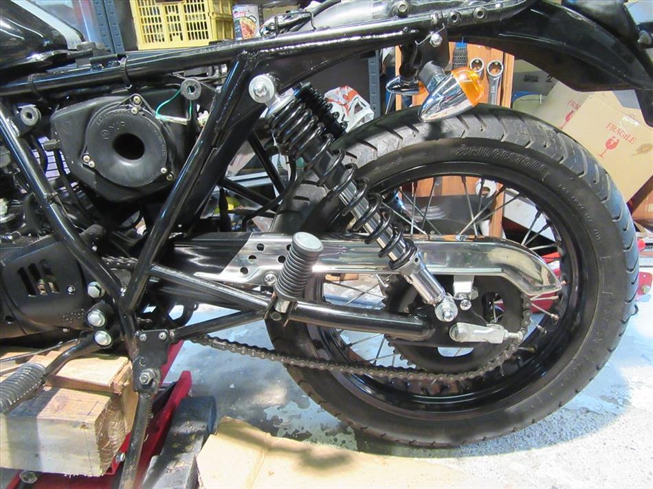
I've fitted a new chain and replaced the original rear suspension units, which are universally derided by experienced owners although looking very pretty, with secondhand units from a Yamaha YS125. They fit perfectly and actually move a bit when I put some weight on the back......
I've just finished fitting a battery charging connector so think I deserve a break.......
 07/06/2026 13:59:55 UTC
Ren - The Ed¹ said :-
That chain looks slack Ian, I hope you're going to adjust that once you've had your break. The near side rear indicator is pointing skywards too.
Otherwise - cool! I look forward to hearing about how it rides and I hope it suits you.
08/06/2026 08:22:06 UTC
Upt'North ¹ said :-
If anybody wants any I can recommend these folks.
Upt.
https://vehicleclips.co.uk/products/suzuki-plastic-clips-for-bike-atv-quad-fende...
08/06/2026 09:12:13 UTC
Ian Soady¹ said :-
Of course Ren. This pic shows how I do it by getting the sprocket, swinging arm spindle and wheel spindle all in line. It's actually a pretty poor design as they will probably only get that far in use under extreme compression but best to set the slack at that point. The previous pic shows it with the wheel off the deck ie at max extension.
Knee still painful although very clowly improving so I hope to be out and about on either (or both) the B'Zuki outfit and the Herald.
 08/06/2026 10:00:11 UTC
Ian Soady¹ said :-
Oh, the indicator is dangling because its fixing bolt holds the seat on: I've removed that for dying it black and didn't bother tightening up the bolt.
08/06/2026 12:59:48 UTC
Ian Soady¹ said :-
Looks much better with the seat dyed black. A good £15 worth. Also given the side panels a couple of coats of gloss lacquer as for some reason they were finished in matt black.
 10/06/2026 11:55:42 UTC
Ian Soady¹ said :-
This was it before. Why anyone would give it a seat that colour beats me.
 10/06/2026 11:56:16 UTC
Ren - The Ed¹ said :-
Looking smart Ian - although I personally have no issue with a brown seat but then I have no style either.
10/06/2026 16:20:46 UTC
Upt'North ¹ said :-
Looking good fella, like Ren, I have little sense of style and taste but the brown and black bike did look a little daft.
Looking forward to your ride report.
Upt.
11/06/2026 10:06:12 UTC
Glyn said :-
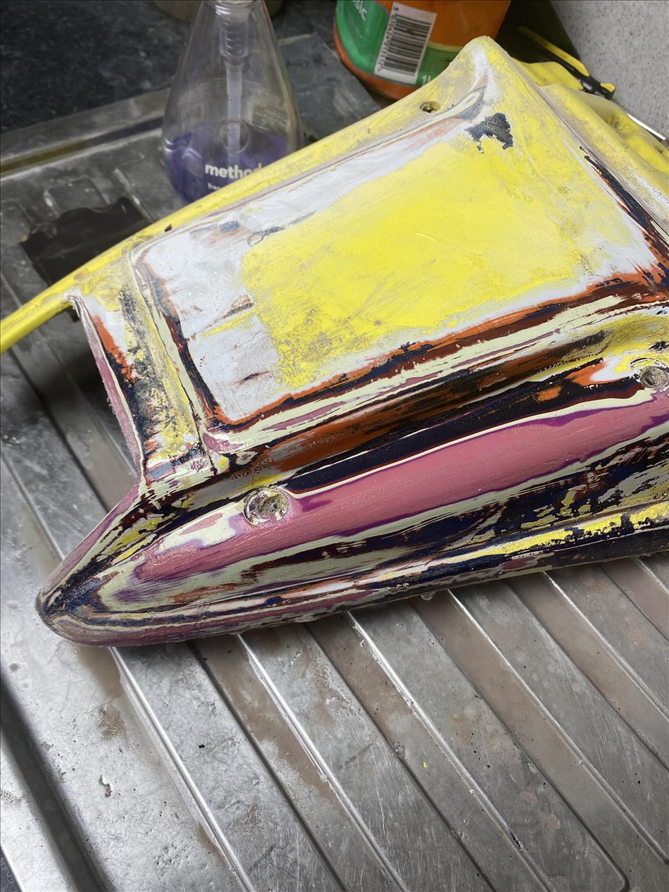
That is a remarkable upgrade for £15 Ian. It looks brand new. Talking about unsuitable colours this is the rear section of the little Aprilia. It has had 14 owners and been 7 different colours.
24/06/2026 07:51:34 UTC
Glyn said :-
Sorry forgot the image
 24/06/2026 07:52:40 UTC
Upt'North ¹ said :-
I wondered where that screwdriver had gone, have you got my 10 mill socket too!
I'd smooth that off and lacquer it as a homage to rattle cans.
You're welcome.
Who'd have thought it, Glyn a screwdriver thief?
Upt.
24/06/2026 09:21:38 UTC
Ian Soady¹ said :-
It's like archaeology (or a time machine) when you get down through the layers like that, and as Upt' says it would be interesting to keep it. But I think that would offend your aesthetic sensibilities.
Re vinyl dye, the Steib came with a seat cover which is red and would clash with the BSA red so will probably dye that black as well. At the moment, the only passenger provision is a box full of pavers left over from a patio to keep the chair wheel down on left handers although this is scorned by some "experts". No idea why as an empty sidecar limits the speed round these bends. I can understand if a passenger is occasionally carried that you need to understand the handling in different configurations.
24/06/2026 10:17:29 UTC
Flyn said :-
Ian is right Up’t, not really my style to clear-coat it. I’ve decided to respray it colour number 8 in Elfenbein 732 which is a BMW ivory colour. Elfenbein is a direct German translation for “Elephants tusk”. It’s the colour that I painted the BMW K1100 2 years back. However, this time there will be no evidence of the colours that went before.
24/06/2026 20:48:49 UTC
Glyn said :-
Oh no I’ve spelt my name wrong again. It’s these fat fingers I’m working with. Talking of fingers, I almost removed the top of my middle finger right hand in an incident with a sun lounger in Croatia 3 weeks ago. It took 5 stitches to reattach and weeks of dressings which I’m still doing. I’ve got some fairly gruesome pictures of aforesaid digit but I’m sure the Ed wouldn’t be impressed if I were to post one.
24/06/2026 20:54:01 UTC
Ian Soady¹ said :-
I managed to slice a couple of mm off a finger with the angle grinder a couple of weeks ago removing the chain from the Herald*. I'm usually very cautious around them but a moment's inattention...... It's taken to now to heal up.
*And what's wrong with split links I ask you? Someone had gone to the length of fitting a continuous O ring chain at some time in the bike's 3,000 km life while studioudly ignoring the dreadful suspension units.
Goldie silencer arrived yesterday and it's in new condition. A bargain at just over £30. It does say pre 1985 bikes but this is invisible when fitted. Too hot for anything today.
25/06/2026 10:13:31 UTC
Ren - The Ed¹ said :-
Ooooh eeeee ouch! I'm glad you didn't post your gory sliced digit Glyn (Flyn). You can show us when it's healed a little and we can imagine the rest. As for the heat... Enough already but it won't be long until I'm griping about the rain/cold dagnammit. The nights are already drawing in.
26/06/2026 09:57:29 UTC
nab301 said :-
Glyn , looking forward to seeing and hopefully hearing the fruits of your labours , will you be stripping the engine?
Nigel
26/06/2026 14:53:36 UTC
Name
Comment
Add a RELEVANT link (not required)
Upload an image (not required) -
Uploading...